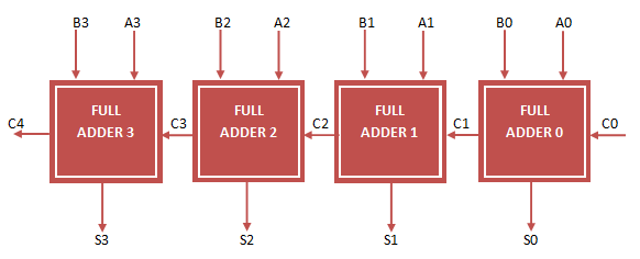
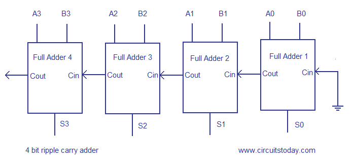
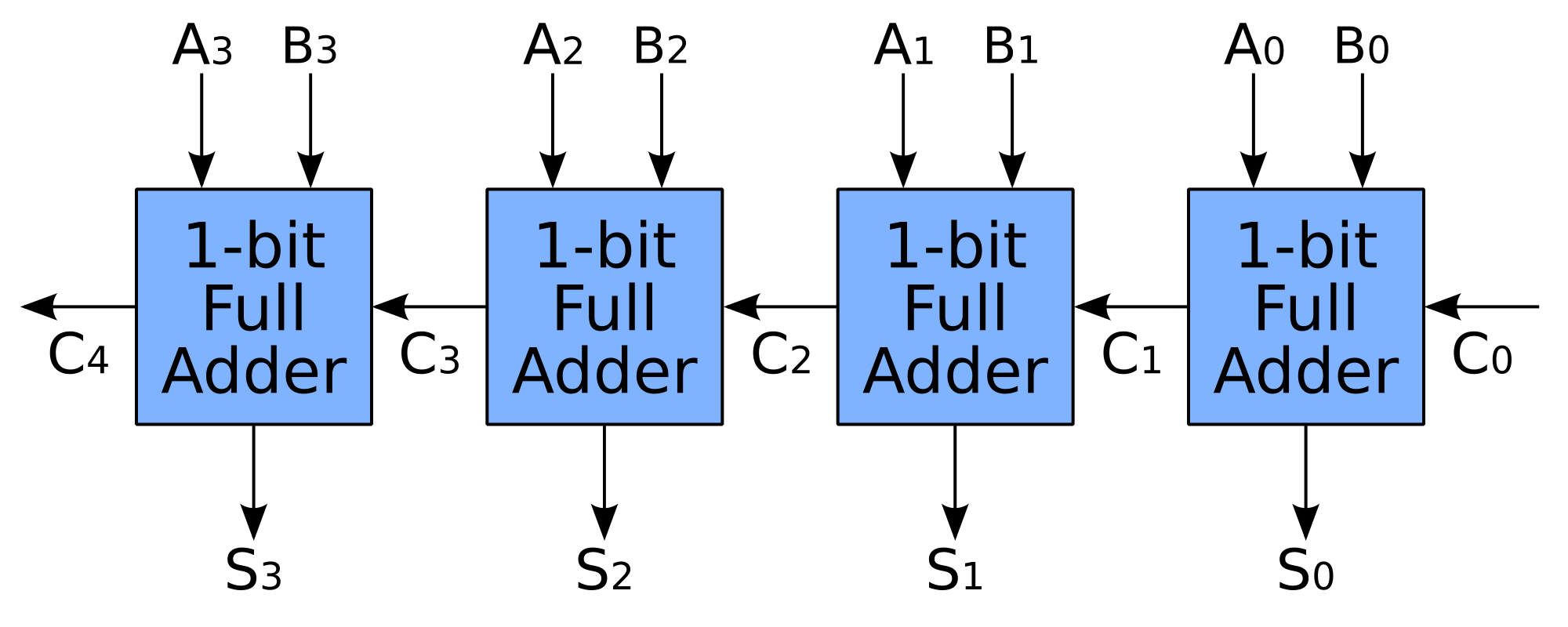
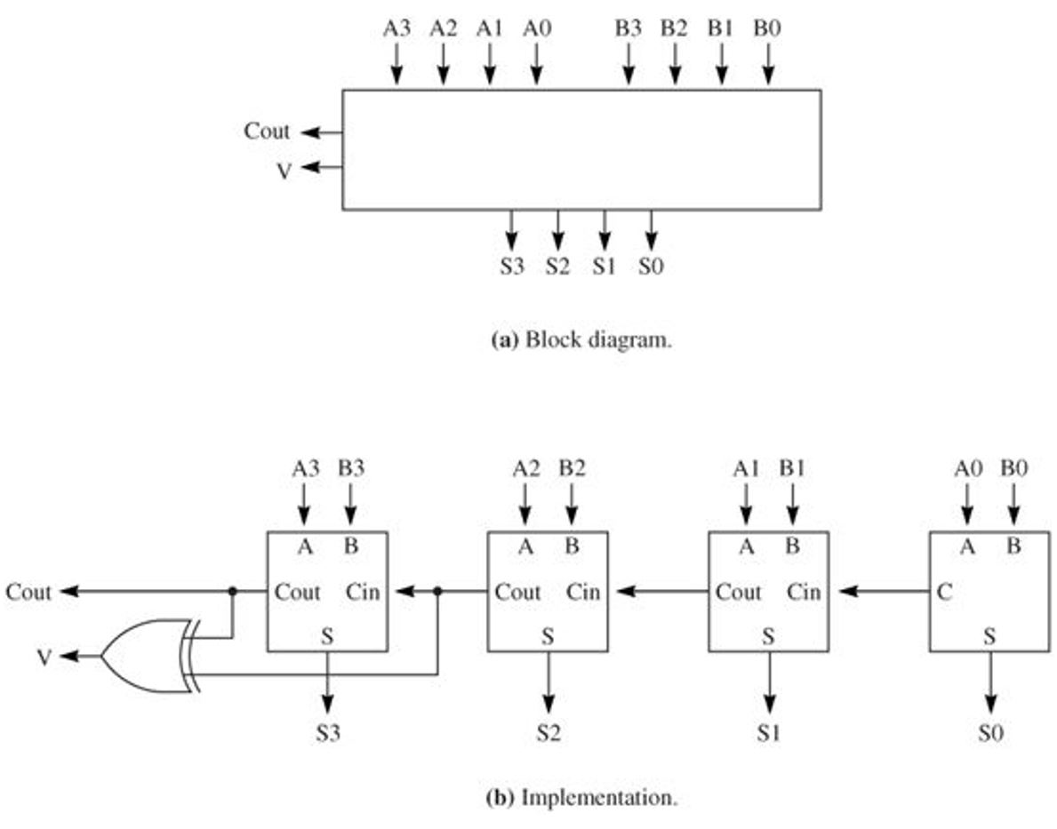
4 bit ripple carry adder
The carry-out represents bit one of the result, while the sum represents bit zero. As can be seen above in the implementation section, the logic for generating 4 bit ripple carry adder carry contains all of the logic used to generate the previous carries. Using only two types of gates is convenient if the circuit is being implemented using simple IC chips which contain only one gate type per chip. Dynamic logic can support shared logic, as can transmission gate logic. Although adders can be 4 bit ripple carry adder for many number representationssuch as binary-coded decimal or excess-3the most common adders operate on binary numbers.
The carry-lookahead adder calculates one or more carry bits before the sum, which reduces the wait time to calculate the result of the larger-value bits of the adder. Then, when the 4 bit ripple carry adder addition is performed, there is no delay from waiting for the ripple-carry effect or time it takes for the carry from the first full adder to be passed down to the last full adder. By using this site, you agree to the Terms of Use and Privacy Policy.

For each bit in a binary sequence to be added, the carry-lookahead logic will determine whether 4 bit ripple carry adder bit pair will generate a carry or propagate a carry. Likewise, a half adder can be used as a 2: It is possible to have more than one level of lookahead-carry logic, and this is in fact usually done.
Passages from the Life of a Philosopher. When adding bit integers, for instance, allowance has to be made for the possibility that a carry could have to ripple through every one of the 32 one-bit adders. The output variables are the sum and carry.
In cases where two's complement or ones' complement is being used to represent negative numbersit is trivial to modify an adder into an adder—subtractor. Accordingly, all digit positions other than the rightmost one need to take into account the possibility of having to add an extra 1 from a carry that has come in from the next position to the right. In most cases, P is simply the sum output of a half adder and G is the carry output of the same adder. Some other multi-bit adder architectures break the adder into blocks. From Wikipedia, the free encyclopedia.

If an adding circuit is to compute the sum of three or more numbers, it can be advantageous to not propagate the carry result. The carry signal represents an overflow into the next 4 bit ripple carry adder of a multi-digit addition. As can be seen above in the implementation section, the logic for generating each carry contains all of the logic used to generate the previous carries.
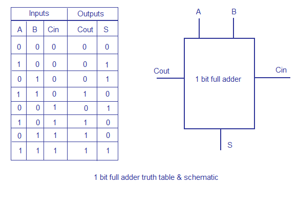
An adder is a digital circuit that performs addition of numbers. The carry signal represents an overflow into the next digit of a multi-digit addition. However, not all logic families have these internal nodes, CMOS being a major example. A ripple-carry adder works in the same way as pencil-and-paper methods of addition. Accordingly, all digit positions other than the 4 bit ripple carry adder one need to take into account the possibility of having to add an extra 1 from a carry that has come in from the next position to the right.

Instead, three-input adders are used, generating two results: From Wikipedia, the free encyclopedia. Sometimes a slightly different definition of propagate is used.
Accordingly, all digit positions other than the rightmost one need to take into account the possibility of having to add an extra 1 from a carry that has come in from the next position to the right. Written at Heverlee, Belgium. To 4 bit ripple carry adder the computation time, engineers devised faster ways to add two binary numbers by using carry-lookahead adders CLA. As can be seen above in the implementation section, the logic for generating each carry contains all of the logic used to generate the previous carries. Finally, within each group that receives a carry, the carry propagates slowly within the digits in that group.
The addition of two 1-digit inputs A and B is said to generate if the addition will always carry, regardless of whether there is an input-carry equivalently, regardless of whether any less significant digits in the sum carry. One 4 bit ripple carry adder the major downsides of the Manchester carry chain is that the capacitive load of all of these outputs, together 4 bit ripple carry adder the resistance of the transistors causes the propagation delay to increase much more quickly than a regular carry lookahead. In most cases, P is simply the sum output of a half adder and G is the carry output of the same adder.