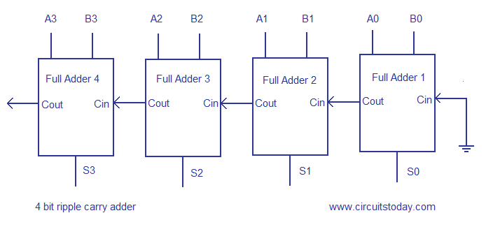
4 bit ripple carry adder circuit diagram
Digital Logic and Computer Design. Such compressors can be used to speed up the summation of three or more addends. It is possible to create a logical circuit using multiple full adders to add N -bit numbers.

After all stages of addition, however, a conventional adder such as the ripple-carry or 4 bit ripple carry adder circuit diagram lookahead must be used to combine the final sum and carry results. This kind of circuit is most notably used in multipliers, which is why these circuits are also known as Dadda and Wallace multipliers. The output variables are the sum and carry. It is possible to create a logical circuit using multiple full adders to add N -bit numbers.

In cases where two's complement or ones' complement is being used to represent negative numbersit is trivial to modify an adder into an adder—subtractor. The input variables of a half adder are called the augend and addend bits. Retrieved from " https:

A full adder can be viewed as a 3: The input variables of a half adder are called the augend and addend bits. This kind of adder is called a ripple-carry adder RCAsince each carry bit "ripples" to the next full adder. The carry-out represents bit one of the result, while the sum represents bit zero.
By combining multiple carry-lookahead adders, even larger adders can be created. Each full adder inputs a C inwhich is the C out of the previous adder. This kind of circuit is most notably used in multipliers, which is why these circuits are also known as Dadda and Wallace multipliers.

The half adder adds two single binary digits A and B. A full adder adds binary numbers and accounts for values carried in as well as out. By using this site, you agree to the Terms of Use and 4 bit ripple carry adder circuit diagram Policy. A full adder can be implemented in many different ways such as with a custom transistor -level circuit or composed of other gates. In most cases, P is simply the sum output of a half adder and G is the carry output of the same adder.