4 bit ripple counter verilog code for latch
The propagation time can be a limiting factor on the speed of the circuit. The simulation results will be unchanged. This example was discussed at a very abstract level in Chapter 2, Hierarchical Modeling Concepts. Notice that instead of the not gate, a dataflow operator - negates the signal q, which is fed back.

The code contains instantiation of four T-FF modules. One of the most popular methods to reduce delay is to use a carry lookahead mechanism. We design it using Verilog dataflow statements and test it with a stimulus module.

An n-bit ripple carry adder will have 2n gate levels. One of the most popular methods to reduce delay is to use a carry lookahead mechanism. The code contains instantiation of four T-FF modules. The propagation time can be a limiting factor on the speed of 4 bit ripple counter verilog code for latch circuit. A Guide to Digital Design and Synthesis If we substitute the gate-level Cbit full adder with the dataflow Cbit full adder, the rest of the modules will not change.

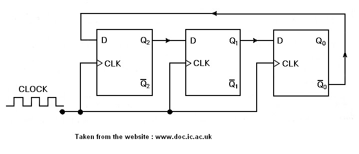
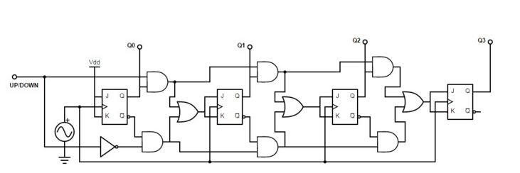
The code is shown in Figure By encapsulating functionality inside a module, we can replace the gate-level module with a dataflow module without affecting the other modules in the simulation. We design a 4-bit ripple counter by using negative edge- triggered flip-flops. The diagrams for the 4-bit ripple carry counter modules are shown below. This is a very powerful feature of Verilog.

First we design the module counter. The code is shown in Figure We design it using Verilog dataflow statements and test it with a stimulus module.