4040 12 bit ripple counter applications

Converting the synchronous up counter to count down is simply a matter of reversing the count. A buffered clock CLK input triggers the four flip-flops on the rising positive-going edge of the clock waveform. This problem is reduced in ripple counters due to the lower 4040 12 bit ripple counter applications in most of the stages. Therefore whenever CTEN is at logic 1 the count is disabled. The circuit is therefore a BCD counter, an extremely useful device for driving numeric displays via a BCD to 7-segment decoder etc.

They are normally shown in schematic diagrams in reverse order, with the least significant bit at the left, this is to enable the schematic diagram to show the circuit following the convention that signals flow from left to right, therefore in this case the CK 4040 12 bit ripple counter applications is at the left. Understand the operation of digital counter circuits and can: Each group of gates between successive flip-flops is in fact a modified data select circuit described in Combinational Logic Module 4.

Synchronous counters therefore eliminate the clock ripple problem, as the operation of the circuit is synchronised to the CK pulses, rather than flip-flop outputs. If 4040 12 bit ripple counter applications already have a simulator such as Logisim installed on your computer, why not try designing an Octal up counter for example. To convert the up counter in Fig. Converting the synchronous up counter to count down is simply a matter of reversing the count. Converting the synchronous up counter to count down is simply a matter of reversing the count.

The synchronous counter provides a more reliable circuit for counting purposes, and for high-speed operation, as the clock pulses in this circuit are fed to every flip-flop in the chain at exactly the same time. The Web This site. Stops count without resetting when at logic 1.

In synchronous counters, with every stage operating at very high clock frequencies, stray capacitive coupling between the counter 4040 12 bit ripple counter applications other components and within the counter itself is more likely occur, so that in synchronous counters interference can be transferred between different stages of the counter, upsetting the count if adequate decoupling is not provided. Asynchronous counters are mostly used for frequency division applications and for generating time delays. After studying this section, you should be able to:

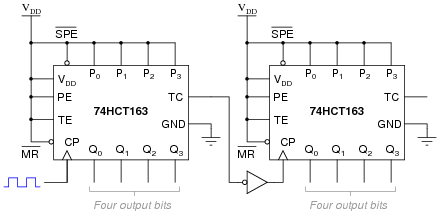
Although it may appear that either the TC or the RC outputs could drive the next clock input, the TC output is not intended for this purpose, as timing issues can occur. In this condition, when the next clock pulse is received at the CK input the flip-flops will toggle, following their normal sequence. The function of the counter whether 4040 12 bit ripple counter applications, disabled, loading, or counting is dictated solely by the conditions meeting the stable setup and hold times.