32 bit ripple carry adder in verilog

The inputs and outputs are listed in the following:. CLAs use generate G and propagate P signals that describe how a column or block determines the carry out. So, we need to include this feature in the top level bit ripple carry adder.

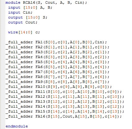
CLAs use generate G and propagate P signals that describe how a column or block determines the carry out. Four 4-bit adder modules are instantiated, as M1, M2, M3, and M4 respectively. Four full-adder modules are instantiated, as M1, M2, M3, and M4 respectively. When reset goes to 1, output sum and crout are reset to 0, and input buffers a and b are reset to 0. The ith column of an adder is guaranteed to generate 32 bit ripple carry adder in verilog carry Ci if Ai and Bi are both 1.
In this way, we can quickly compute the carry out of the block, Ci, using the carry in to the block Cj. The simplest way to build an N-bit carry propagate adder is to chain together N full adders. Clock and reset are for sequential block; op1 and op2 are two bit inputs. The design has clock and reset signal as inputs. Cout from previous adder is propagated to next adder as Cin.
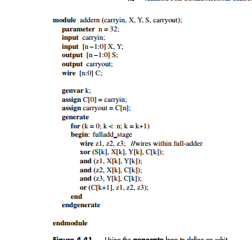
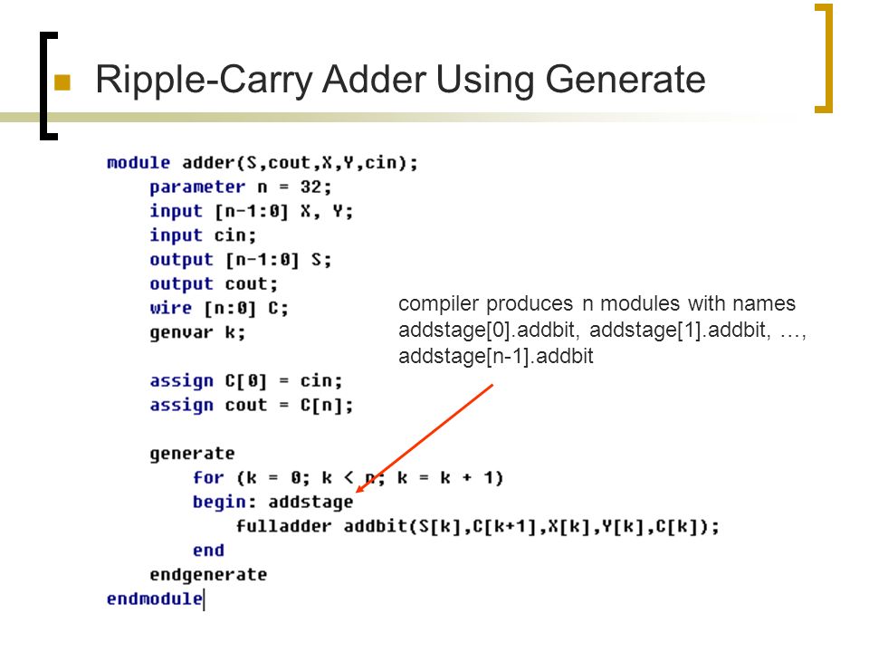
So, we need to include this feature in the top level bit ripple carry adder. Clock and reset are for sequential block; op1 and op2 are two bit inputs. We can build a full 32 bit ripple carry adder in verilog first, and then chain four full adders together to build a 4-bit adder, and chain 4-bit adders together to build a bit adder, and then to build a bit adder. For a 4-bit carry lookahead adder, the propagate logic is. In this way, we can quickly compute the carry out of the block, Ci, using the carry in to the block Cj.
Sum is a bit output and crout stands for carry out, which is 1 bit. Clock and reset are for sequential block; op1 and op2 are two bit inputs. Large ripple-carry adders are slow is that the carry signals must propagate through every bit in the adder. Ran logic 32 bit ripple carry adder in verilog, wrote Perl script to run synthesis, ran gate-level simulation, and performed STA using Primetime.

A carry- lookahead adder CLA is another type of carry propagate adder that solves this problem by dividing the adder into blocks and providing circuitry to quickly determine the carry out of a block as soon as the carry in is known. Cout from previous adder is propagated to next adder as Cin. So, we need to include this feature in the top level bit ripple carry adder. Four full-adder modules are instantiated, 32 bit ripple carry adder in verilog M1, M2, M3, and M4 respectively. CLAs use generate G and propagate P signals that describe how a column or block determines the carry out.

Four full-adder modules are instantiated, as M1, M2, M3, and M4 respectively. The 4-bit is consisted of four 1-bit adders. A block propages a carry 32 bit ripple carry adder in verilog all the columns in the block propagage the carry. We can build a full adder first, and then chain four full adders together to build a 4-bit adder, and chain 4-bit adders together to build a bit adder, and then to build a bit adder.
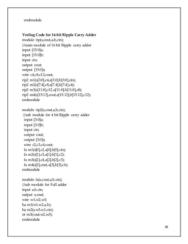
Otherwise, at every positive edge of clock signal, a and b take values from op1 and op2, sum and crout take values from sumbuffer and croutbuffer. The Verilog for 4-bit adder is in the following:. This is asynchronous reset. Ripple Carry Adder The simplest way to build an N-bit carry propagate adder is to chain together N full adders.
This is the sequential part. The following part instantiates four bit ripple carry adders, stores the sum result into sumbuffer, and stores carry out result into croutbuffer. Large ripple-carry adders are slow is that the carry signals must propagate through every bit in the adder. Sum is a bit output and crout stands for carry out, which is 1 bit.

CLAs use generate G and propagate P signals that describe how a column or block determines the carry out. For a 4-bit carry lookahead adder, the propagate logic is. Ran logic simulation, wrote Perl script to run synthesis, ran gate-level simulation, and performed STA using Primetime.